INTEGRAL HYDRAULIC COMPONENTS

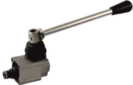
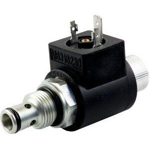
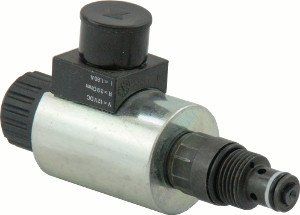
By integral hydraulic components we mean the range of cartridges that are screwed directly into the cavities of the central body to create the desired hydraulic scheme. These are pressure, direction and flow control valves, hand pump and caps to block or open the required passages.

Manual cartridge pump

The PMC02 SAE08 (3 / 4-16UNF) 2cc cartridge hand pump is a simple and economical way to add an emergency activation of the control panel.

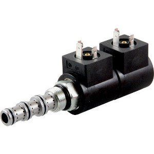
Two-way solenoid valves


Two-way solenoid valves with SAE08 (3 / 4-16UNF) sealed poppet seat. They are available normally closed, open with single and double seal. Manual override is also available.

Proportional valves

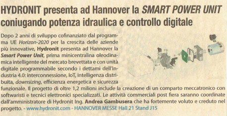
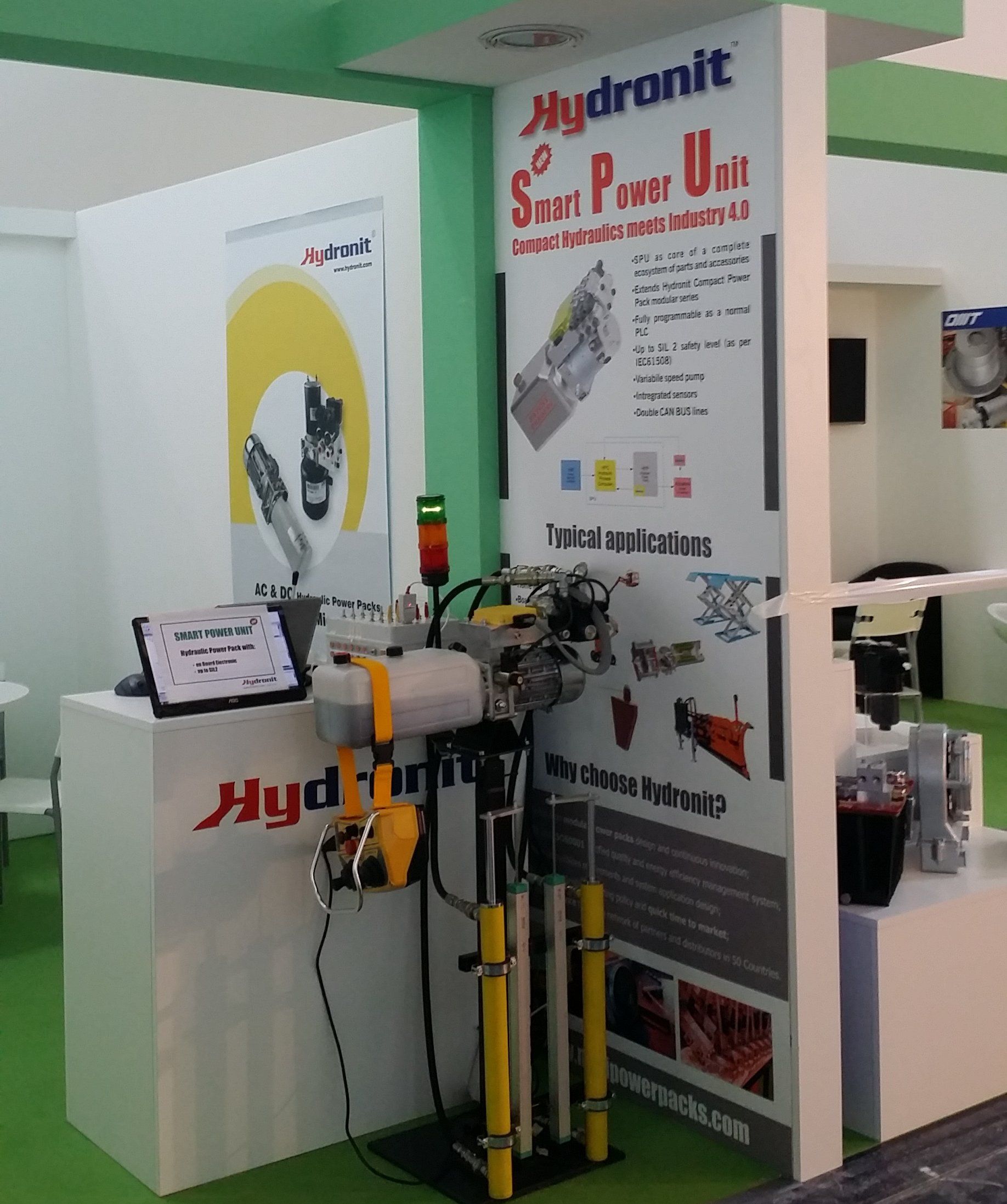
Proportional pressure, flow and direction control valves are available. The valves can be driven directly by the electronics of the Smart Power Unit (up to 12 solenoids of 2A each) or, in the case of conventional control units, by means of a PWM driver that can be positioned directly on the valve.

Maximum pressure valves

The main safety valve is mounted in a SAE08 cavity (3 / 4-16UNF) for the PPC series and M14 for the PPM series. Relief valves are designed to optimize regulation and operating stability, avoiding the noisy operation typical of low cost alternatives.

Direction control solenoid valves


Available in two, three and four ways, with coils from 18-22W to 12V DC, 24V DC, 48V DC, 115V AC, 230V AC

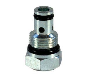
Main check valves

The main check valve fits into a standard SAE08 cavity (3 / 4-16UNF) for the PPC series and 5 / 8-18 UNF for the PPM series and can be easily removed from the outside for easy cleaning and maintenance.

Common questions

Below you can find the most common questions and answers, or you can call us at Tel. 39.0362.1841.210
  • How is the control panel coding defined?

    The control units are coded with a "talking" code, which is basically the list of the sub-groups that make up the control unit (engine, pump, valves, tank, ...). The integral components are those mounted inside the central cavities of the manifold, numbered. Each component has an assembly code, usually a single letter, which constitutes the speaking code. It also has a spare part number in case it is to be ordered as a loose component. The numbered cavities are indicated in the hydraulic diagram and also on the casting, so that it is easy to draw the diagram starting from the speaking code itself and to easily mount the components on the manifold.

  • There are several coils and connectors for cartridge solenoid valves. How do I choose the right ones?

    Thanks to the consistency of the Hydronit range, most integral solenoid valves are fitted with the same coils as the M63 * series. M630 are for DC supply voltage, while M631 are rectified coils with integrated diode to be powered directly with alternating current, without external rectifier bridge. M63 * coils are available with standard DIN 43650 / ISO 4400 (KA13200000) connectors and Deutsch connectors.

  • What are the most used caps?

    The plugs allow you to modify the internal passages of the central bodies in order to create the desired hydraulic circuit. In bodies U, the plugs G or H are normally mounted in the cavities 2 and 4 of the central manifolds type UA and UB, when these cavities are not used. Type H has a 1/4 "BSP connection port to allow mounting of a pressure gauge, pressure switch or minimess. Type L plug fits cavity 3 of U4 and UB manifolds when this cavity is not in use.

Share by: